Heat Treatment Processes:-
Heat treatment of steels is the heating and cooling of metals to change their physical and mechanical properties, without letting it change its shape. improving formability, machining, etc.
Heat Treatment Process Steps:-
In simple terms, heat treatment is the process of heating the metal, holding it at that temperature, and then cooling it back. During the process, the metal part will undergo changes in its mechanical properties. This is because the high temperature alters the microstructure of the metal. And microstructure plays an important role in the mechanical properties of a material.
Holding:-
During the holding, or soaking stage, the metal is kept at the achieved temperature. The duration of that depends on the requirements.
For example, case hardening only requires structural changes to the surface of the metal in order to increase surface hardness. At the same time, other methods need uniform properties. In this case, the holding period is longer.
Cooling:-
After the soaking stage is complete, the metal must be cooled in a prescribed manner. At this stage, too, structural changes occur. A solid solution on cooling may stay the same, become a mechanical mixture completely or partially, depending on various factors.
Different media such as brine, water, oil or forced air control the rate of cooling. The sequence of cooling media named above is in decreasing order of effective rate of cooling. Brine absorbs heat fastest, while air is the slowest.
Hardening:-
Hardening involves heating of steel, keeping it at an appropriate temperature until all pearlite is transformed into austenite, and then quenching it rapidly in water or oil. The temperature at which austentizing rapidly takes place depends upon the carbon content in the steel used. The heating time should be increased ensuring that the core will also be fully transformed into austenite. The microstructure of a hardened steel part is ferrite, martensite, or cementite.
Phase Diagrams
Each metal alloy has its own phase diagram. As previously said, heat treatment is done according to these diagrams. They show the structural changes that take place at different temperatures and different chemical compositions.
Let’s use the iron-carbon phase diagram as an example, as this is the most known and widely taught one at universities.
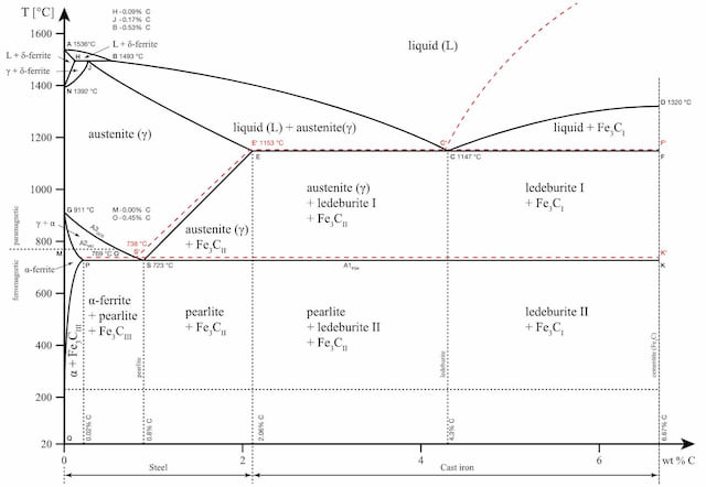
The iron-carbon phase diagram is an important tool when learning about the behaviour of different carbon steels when subjected to heat treatment. The x-axis shows the carbon content in the alloy and the y-axis shows the temperature.
These regions are marked by boundaries A1, A2, A3, and Acm. At these interfaces, phase changes occur when the temperature or carbon content value passes through them.
A1: The upper limit of the cementite/ferrite phase.
A2: The limit where iron loses its magnetism. The temperature at which a metal loses its magnetism is also called Curie temperature.
A3: The interface that separates Austenite + Ferrite phase from the γ (Gamma) austenite phase.
Acm: The interface that separates γ Austenite from the Austenite + Cementite field.
The phase diagram is an important tool to consider whether heat treatment will be beneficial or not. Each structure brings along certain qualities to the final product and the choice of heat treatment is made based on that.
Tempering:-
Tempering Tempering involves heating steel that has been quenched and hardened for an adequate period of time so that the metal can be equilibrated. The hardness and strength obtained depend upon the temperature at which tempering is carried out. Higher temperatures will result into high ductility, but low strength and hardness. Low tempering temperatures will produce low ductility, but high strength and hardness.
Comments
Post a Comment